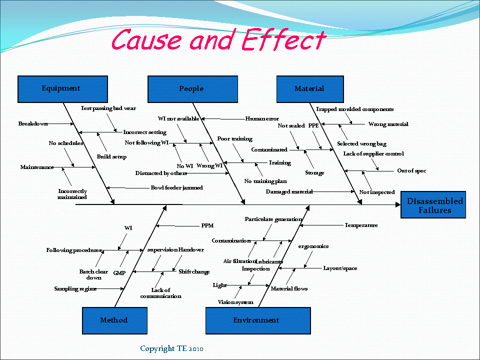


Operators are the most common group in this category, but it can also include maintenance teams, quality control specialists and supervisors. This category is for anything related to the people associated with the process. For a great example, see the American Society for Quality (ASQ) glossary entry on fishbone diagrams. It’s worth noting that each category may also have various sub-causes as well. Under each category is where you add elements that could impact the process associated with that cause.

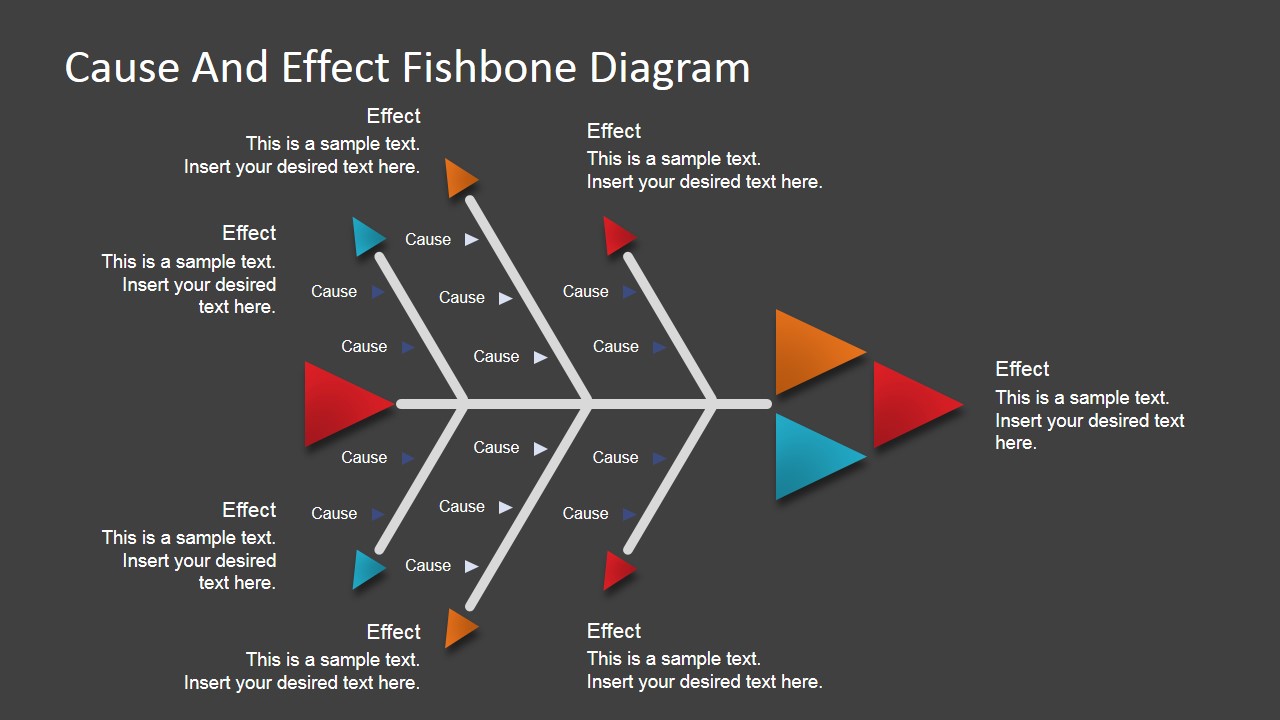
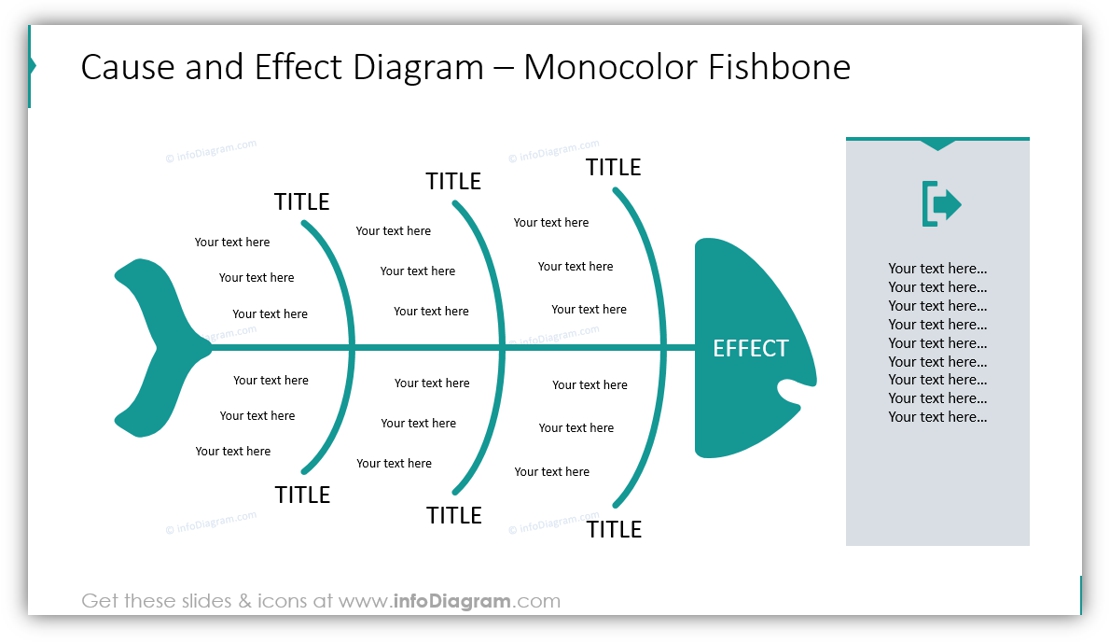
While the categories can change, the most commonly used are: Each of the bones feeding into the spine of the fish represents a specific category of potential contributors to the problem. Over time, it was nicknamed the fishbone diagram due to its resemblance to a fish skeleton laid on its side. It is considered part of The Basic Seven tools of quality control today. Popularized in the 1960s, the Ishikawa diagram was used as a basic tool of quality control by Kaoru Ishikawa at the University of Tokyo.
ISHIKAWA DIAGRAM CAUSE AND EFFECT FREE
Easily create, customize, and present your own fishbone diagram with our free downloadable set of templates!Ī fishbone diagram, also called an Ishikawa diagram, is a visual method for root cause analysis that organizes cause-and-effect relationships into categories.
ISHIKAWA DIAGRAM CAUSE AND EFFECT HOW TO
Here we look at the basics of how a fishbone diagram works, as well as some examples of how to apply it in your facility. Using this method allows you to visualize and organize potential causes of a problem into a useable framework for solving it. One visual method of root cause analysis that helps do just that is the fishbone diagram. However, without a way to organize the information visually, it can be hard to see how different facets of the problem interact. When tasked with solving a problem, brainstorming potential causes is a good place to start.


 0 kommentar(er)
